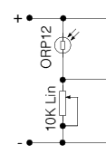
 | Many "control" circuits are triggered by a signal which is produced by a "potential divider" network.
The signal value depends upon the component values and the supply voltage:
Vs=V*R2/(R1+R2)
where:
Vs is the signal value
V is the supply voltage
R1 is the resistance between the positive supply rail and the base of the transistor
R2 is the resistance between the negative supply rail and the base of the transistor
L.D.Rs decrease their resistance with an increase in light intensity. As light increases, therefore, the resistance of the LDR decreases and allows the voltage at the base of the transistor to move closer to that of the positive supply rail.
A signal of 0.6V, or greater, to the BASE of the transistor "switches on" the transistor and allows a current to flow in the COLLECTOR / EMITTER circuit.Transistors also act as CURRENT AMPLIFIERS since a small base current (Ib) controls a much larger collector current (Ic). The amplification (GAIN - hfe) of a transistor, is given by the equation hfe = Ic/Ib and is typically several hundreds. Note that the use of a variable resistance in the other half of the potential divider circuit allows the sensitivity of the curcuit to be adjusted.
N.B. When choosing a transistor it is important to make sure that the gain is high enough for the required use and that the maximum current which it can handle is sufficient to drive the output device. e.g. BFY 51 gain > 40 , max Ic = 1 amp.
If the max Ic value is exceeded, the transistor will probably "burn out".
The transistor acts as a NOT gate (inverter) since a "high" at the base gives a "low" at the collector. (When the transistor switches on, the collector voltage decreases.)
|


